


High temperature NAND-Flash
Introduction:The chip is high-temperature NAND-Flash memory, with fast reading and writing, high reliability, excellent performance characteristics under both of high and low temperature. It can Operate in -45 ℃ ~ 175 ℃ in harsh environment for Long-term. Noted: ( Capacity: 4GA, no magnet, no encryption).
Product Introduction:
Model | Voltage | Structure | Package |
LDMF1GA | 2.7V~3.6V | 1G x 8 bit | DIP16 |
LDMF4GA | 2.7V~3.6V | 4G x 8 bit | DIP16 |
Features:
Operating temperature: The highest operating current: Standby current: Operating Voltage Range(Vcc): Input High level (V): Input Low level (V): Output High level (V): Output Low level (V): High temperature data hold time: Operating life: Read/write Rate: Package: | ﹣45℃ ~ ﹢175℃ 90mA <2mA 2.7 V ~ 3.6 V 0.8Vcc ~ Vcc﹢0.3 ﹣0.3 ~ 0.2Vcc 2.4 ~ Vcc ﹣0.3 ~ 0.4 ≥500h ≥2000h 2.8 ms/page read 2. 15ms/page write 16 PIN DIP PB-Free Package |
Application:
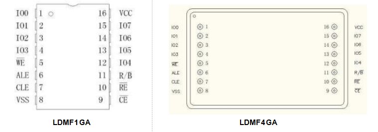
Pin Description:
Technical Specification:
PIN | Functional description |
IO0 ~ IO7 | Multiplexed input / output The bidirectional I/Os transfer address, data, and command information. — — When CE pin is high ,the I/Os is High impedance. |
CLE | Command Latch Enable When CLE is high, the command is latched into the command register through the IO port on the rising edge of the WEsignal. |
ALE | Address Latch Enable When ALE is high ,the address is latched into the address register through the IO port on the rising edge of the WEsignal. |
CE | Chip Enable Enables or disables the chip. |
RE | Read Enable Control the output of serial data. When the signal is low, the data is driven — — to the IO port. Data is valid after tREA time on the falling edge of RE, and the internal column address counter is incremented automatically. |
WE | Write Enable Control the input of serial data ,command, address and data is latched on — — the WE Rising edge. |
R/B |
Ready/Busy output Indicates the device operating state. When low, indicates that programming, erase, or random read operation is in progress, when high, indicates that no operation or operation is finished. It is recommended to connect a pull-up resistor (4.7K~ 10K) to the pin. |
Vcc | Power Supply |
Vss | GND |