GDS900 Gyro Based Directional Sensor User Manual
GDS900 GYRO based directional sensor is a new type of inclinometer for measuring well inclination and azimuth Angle. It can be widely used in oil, coal, geology and other logging fields, and can also be used in measurement while drilling. Common inclinometer mainly relies on magnetic sensor to measure the azimuth.
Product Introduction:
In the magnetic mine area, vertical well dense area, casing and other scenarios, the magnetic sensor is easily affected by the magnetic field, and the azimuth Angle is difficult to measure. The GDS900 gyroscope inclinometer is equipped with sensitive devices such as high-precision accelerometer and high-precision gyroscope, which can accurately measure the inclination and azimuth in the case of magnetic interference. Among them, the three-axis accelerometer calculates the inclination Angle (top Angle) and the gravity tool face Angle through the algorithm, and the three-axis gyroscope calculates the azimuth Angle with theassistance of the accelerometer. All logging angles are uploaded through the RS485 interface.
Features:
● High precision
● gyro self-finding north, three-axis accelerometer
● magnetic mining area, casing, steel pipe in normal use
● compact structure and small size
● Vibration and shock resistance
Application:
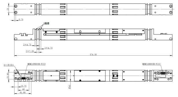
Overall dimension:

Technical Specification:
Table 1. Technical Parameter
Parameter | Test Condition | Standard Value | Unit |
Azimuth range | - | 0~360 |
° |
Azimuth accuracy | 0.5°≤deviation≤50° | ±1 | |
50°≤deviation≤80° | ±1.5 | ||
Deviation range | - | 0~ 180 | |
Deviation accuracy | 0~ 180° | ±0.1 | |
Gravity tool face Angle accuracy | Well deviation>3° | ±2 | |
Gyroscopic tool face Angle accuracy | Well deviation ≤3° | ±3 | |
Gravitational sum | -40~+85℃ | 0.997~ 1.003 | G |
Operating temperature range |
- | -40~+85 | ℃ |
Storage temperature range | - | -40~+85 | |
Input voltage range | - | 12~36 | V |
North seeking time | - | <150 | S |
Power consumption in north seeking |
- | <7 | W |
Power consumption when not seeking north |
- | <1 | W |
Insulation resistance | 50V | 50 | MΩ |
Communication interface | - | RS485 | - |
Baud rate |
- | 115200~460800, default 230400 | bps |
Vibration resistance | - | 12g , 20~2000Hz | - |
Impact resistance |
- | 0.5ms, half sine wave, 1000g |
- |
dimension | - | 135× 19×25mm | mm |
Connection definition
Communication port type: Communication port RS485 port.
Figure 2. Connector 1(MDM21PH003B) Interface definition
No. | Definition | Instruction |
1 | VDD | Power |
2 | GND | Ground |
| 3 | A | RS485 communication interface A |
4 | B | RS485 communication interface B |
5 | 5 | Double through wire, 5 、6 twisted pair |
6 | 6 | Double through wire,5 、6 twisted pair |
7 | 7 | Double through wire, 7 、8 twisted pair |
8 | 8 | Double through wire, 7 、8 twisted pair |
9 | 9 | Double through wire, 9 、 10 twisted pair |
10 | 10 | Double through wire, 9 、 10 twisted pair |
11 | 11 | Through wire |
12 | 12 | Through wire |
13 | 13 | Through wire |
14 | 14 | Through wire |
15 | 15 | Through wire |
16 | 16 | Through wire |
17 | 17 | Through wire |
18 | 18 | Through wire |
19 | 19 | Through wire |
20 | 20 | Through wire |
21 | 21 | Through wire |
Table 3. Connector 2(MDM21SH003B) interface definitions
Number | Definition | Instruction |
1 | NC | NC |
2 | NC | NC |
3 | NC | NC |
4 | NC | NC |
5 | 5 | Double through wire, 5 、6 twisted pair |
6 | 6 | Double through wire, 5 、6 twisted pair |
7 | 7 | Double through wire, 7 、8 twisted pair |
| 8 | 8 | Double through wire, 7 、8 twisted pair |
9 | 9 | Double through wire, 9 、 10 twisted pair |
10 | 10 | Double through wire, 9 、 10 twisted pair |
11 | 11 | Through wire |
12 | 12 | Through wire |
13 | 13 | Through wire |
14 | 14 | Through wire |
15 | 15 | Through wire |
16 | 16 | Through wire |
17 | 17 | Through wire |
18 | 18 | Through wire |
19 | 19 | Through wire |
20 | 20 | Through wire |
21 | 21 | Through wire |


