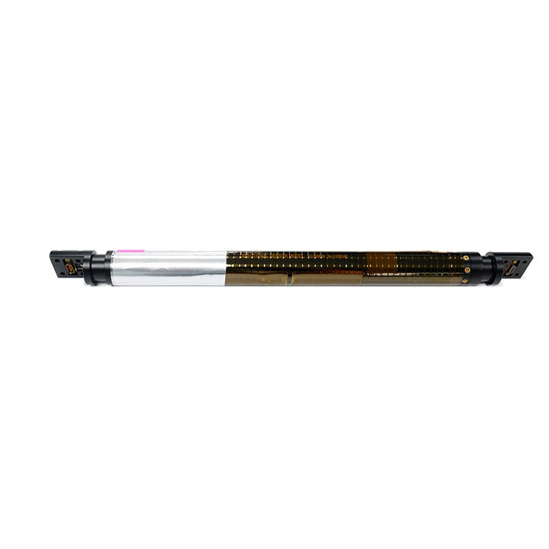
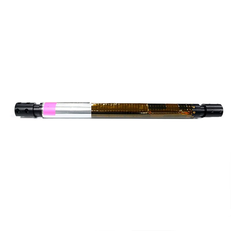
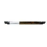
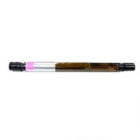
DS750BT High temperature directional sensor Operating manual
● Reliable work is guaranteed in the full temperature range from 0 to 175 ℃
● impact resistance
● vibration resistance
● Digital data transmission
Product Introduction:
This manual introduces the DS750BT high temperature directional sensor dimensions, performance parameters, software parameters configuration method and communication protocol.
Features:
DEVICE DESCRIPTION
The DS750BT high temperature directional sensor consists of a 3-axis fluxgat meter and a 3-axis accelerometer.The inclination angle and the angle of the gravity tool surface were measured by the 3-axis accelerometer. the sensor azimuth angle was measured by the
three-axis flux-gate. The measurement accuracy of the inclination angle and angle of the
gravity tool surface was ±0.1°, and the measurement accuracy of the azimuth angle was
±0.3° .In addition, the sensor can also measure the total adding speed, the total magnetic field strength, magnetic tool surface angle, geomagnetic inclination angle and temperature.
DS750 uses ASCII description instruction language to communicate through two-way TTL interface.The DS750 software includes an automatic send data mode.
Application:
Boundary Dimension:
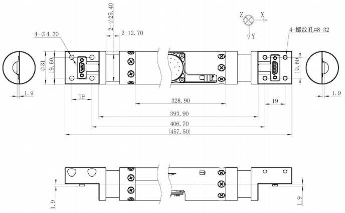
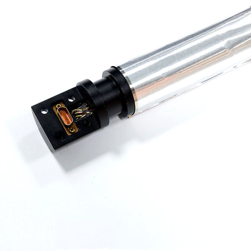
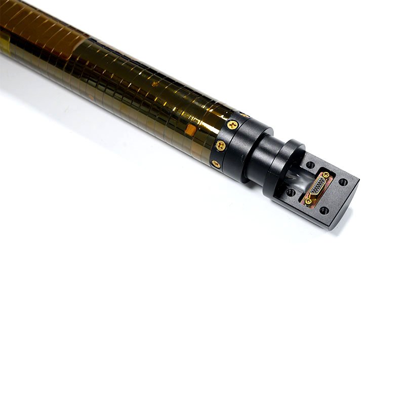
Electrical Interface:
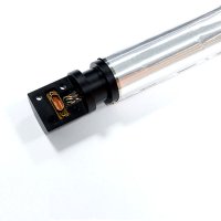
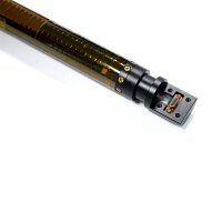
The DS750 uses an MDM connector, and the functions of the connector pinouts are shown in chart 2.The input voltage range of DS750 is +10V~+36V, which adopts UART or RS232 serial communication interface, in which UART interface is compatible with TTL and CMOS level.The default is 9600 baud rate, with a stop bit and no synchronization bit. The user can change the baud rate by setting the parameters in the sensor EEROM.The DS750 can use two communication protocols:
1) the ASCII
The ASCII protocol is based on sending ASCII characters (instructions) to the DS750 to get data.In response to instructions, data is sent as ASCII data streams including carriage returns and line feeds, easily displayed on a computer display terminal (the UART interface sensor is connected to the computer via a TTL to RS232 converter).
2)Binary
The binary protocol is used for high-speed data transfer between MCUS.In this mode, one byte is sent to request the data, and the DS750 responds with a multi-byte packet containing the required data, data header, checksum, and data tail.
DS750 MDM connector pinouts definition as shown in chart 2, which has a connector between the up and down through line, some through wire twisted together by sensors, avoid penetration influence on magnetic flux gate line current, you need to use the twisted together line as the power cord, and through the current should not be too large, up and down the connector of the power input and output power line inside the sensor directly connected.
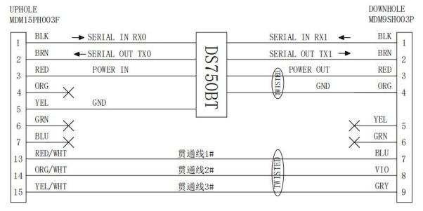
Technical Specification:
Parameters Performance:
Measurement Accuracy | |
Inclination angle | ±0.1° |
tool face angle | ±0.2°@INC=90° |
Azimuth angle |
±0.3°@ INC=90° ±1° @ INC= 10° ±2° @ INC=5° |
Electrical Performance | |
Input voltage range | +10V~+36V |
Input current | <75mA@+15V; |
Digital interface | UART/RS232 optional |
Baud rate | 1200~ 115200 |
Communication protocol | ASCII or Binary |
Working Environment | |
Working environment range | 0~ 150℃ |
Storage temperature range | -40~+160℃ |
Shock | 1000g ,1ms half sine |
Vibration | 20g |
Computer interface:
The communication interface of DS750 sensor is UART (TTL/CMOS compatible) serial interface.In the standard configuration, data is transmitted to the DS750 via the foot RX terminal and output from the DS750 via the foot TX.The default baud rate value is 9600, with a stop bit and no parity bit.
In order to communicate with an external PC, the TTL interface of the DS750 must be converted to an RS332 interface, suitable for all PC serial interfaces.
1 DS750 binary constants and how to set them
The DS750 running mode is controlled by internal binary constants.
Table 1 description of binary constants
Binary constants | Numerical Value | Description |
01 | 5a | Enable automatic send mode |
02 | 02 | Sensor component |
04 | Output of the angle | |
08 | 10 | Automatically send ASCII format data after power on |
09 | Baud rate lock, must be 5a to change the baud rate other than 9600 | |
10 | Setting baud rate .See table 2. | |
20 | Setting output filter | |


