


Orientation sensor for the shortage during drilling DS580T
This manual describes the dimensions, performance parameters, software parameter configuration methods and communication protocols of the DS580T micro directional sensor.
Product Introduction:
The DS580T miniature directional sensor consists of a 3-axis fluxgate sensor and a 3-axis MEMS acceleration sensor. Built- in temperature compensation allows the sensor to measure incline to ±0.1° and azimuth to ±0.5° in the range of 0 to 125 ° C. In addition, the sub can also measure the MWD battery voltage, total charging speed, total magnetic field strength, magnetic toolface Angle, geomagnetic dip Angle, temperature and other parameters. DS580T has the characteristics of small size, high precision, anti-vibration and anti-impact. The DS580T can correct the Angle deviation caused by mechanical installation through the supporting PC software. It can be measured under vibration, and the measurement accuracy is guaranteed when the peak vibration acceleration is less
than 6g.
Features:
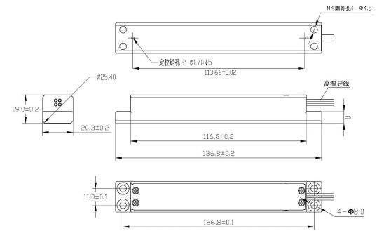
Boundary dimension
Electrical interfaces
The DS580T lead definition functions are shown in Table 2. DS580T input voltage range is +4.9V~+12V, using UART seria l communication interface, TTL logic level +3.3V interface.
The default baud rate is 9600, with one stop bit and no parity bit. You can change the baud rate by setting parameters in the EEROM.
Send 1 byte to request data, DS580T reply with multi-byte packet, packet including required data, data header, check bit sum and data tail, send request instruction frequency up to 10 times /s.
Table 2 Lead arrangement
No. | Code | Definition | Color |
1 | Vin | Power input | Red |
2 | GND | Ground | Black |
3 | TX | Serial data out | Yellow |
4 | RX | Serial data entry | Orange |
Application:
Computer interface
The communication interface of DS580T sensor is UART (+3.3VTTL) serial interface. In the standard configuration, data is transferred to the DS580T viathe RX terminal and output from the DS580T via the TX terminal. The default baud rate is 96
00, with one stop bit and no parity bit.
DS580T parameters and setting methods
DS580T operation mode is controlled by internal parameter values.
Table 1 Parametric description
Parameter (HEX) | Value(HEX) | Description |
01 | 5A | Start automatic send mode, write 00 to close. |
02 | 02 | Sensor component in ASCII format, write 00 to close. |
04 | Angle output ASCII format, write 00 to close. | |
08 | 10 | After power-on,automatic send ASCII format,write 00 to close. |
09 | Baud rate lock, must be 5a to change the baud rate beyond 9600. | |
10 | Baud rate settings, see Table 2. | |
Baud Rate Setting
The default baud rate for DS580T communication is 9600. You can set the baud rate by performing the following steps: 1. Set Parameter 10 according to Table 2.
2. Set parameter 09 to 0x5a.
3. Power on the device again.
For example, the following instruction describes setting the baud rate to 115200
Technical Specification:
No. | Parameter | Stand | |
1 | Measuring range of the inclination | 0°~180° | |
2 | Inclination | ±0.1° | |
3 | Measuring range of azimuth | 0°~360° | |
4 |
Azimuth | Inclination≥5° | ±2° |
Inclination≥10° | ±1° | ||
Inclination=90° | ±0.5° | ||
5 | Measuring range of tool face | 0°~360° | |
6 | Tool face angle | ±0.2°(Inclination=90°) | |
7 | Battery voltage measurement range | 0~36V | |
8 | Compensation temperature scope | 0℃~125℃ | |
9 | Operating temperature range | -40℃~+125℃ | |
10 | Input voltage range | +4.9~+12V | |
11 | Power current | ≤50mA(Vin=+5V) | |
12 | Baud rate | 9600~115200bps | |
13 | Communication interface | TTL(+3.3V) | |
14 | Shock(no power) | Half sine ,2000g ,0.5ms | |
15 | Vibration(no power) | 30g ,Random. | |